Abstract
We propose a novel transform, an expansion of an arbitrary function onto a basis of multi-scale chirps (swept frequency wave packets). We apply this new transform to a practical problem in marine radar: the detection of floating objects by their "acceleration signature" (the "chirpyness" of their radar backscatter), and obtain results far better than those previously obtained by other current Doppler radar methods. Each of the chirplets essentially models the underlying physics of motion of a floating object. Because it so closely captures the essence of the physical phenomena, the transform is near optimal for the problem of detecting floating objects.
Besides applying it to our radar image processing interests, we also found the transform provided a very good analysis of actual sampled sounds, such as bird chirps and police sirens, which have a chirplike nonstationarity, as well as Doppler sounds from people entering a room, and from swimmers amid sea clutter.
For the development, we first generalized Gabor's notion of expansion onto a basis of elementary "logons" (within the Weyl-Hiesenberg group) to the extent that our generalization included, as a special case, the wavelet transform (expansion in the affine group). We then extended that generalization further to include what we call "chirplets". We have coined the term "chirplet transform" to denote this overall generalization. Thus the Weyl-Hiesenberg and affine groups are both special cases of our chirplet transform, with the "chipyness" (Doppler acceleration) set to zero.
We lay the foundation for future work which will bring together the theories of mixture distributions (Expectation Maximization) and our "Generalized Logon Transform".
Keywords: Time-Frequency, chirplet, chirp, logon, Gabor, wavelet, Doppler, Expectation-Maximization.
Gabor's "Logon" Paradigm
Gabor proposed an expansion of a signal onto a set of bases which he illustrated by way of "logons", which are portions of a Time-Frequency (TF) space1 He showed that an arbitrary signal can be decomposed onto a set of functions which are all just modulated versions of a single Ganssian
1Although the logon representation is not a "frame" [1], and is therefore not numerically stable, we proceed in the development of this line of thought, and will later address the issue of numerical stability by overrepresenting the expansion.
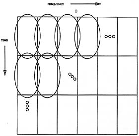
Figure 1: Logon representation of a "complete" set of Gabor bases of relatively long duration and narrow bandwidth. We use the convention of frequency across and time down (in contradiction to musical notation) since our programs that produce, for example, sliding window FFTs, compute one short FFT at a time, displaying each one as a raster line as soon as it is computed.
envelope. This notion is known formally in the physics literature as the Weyl-Hiesenberg group. (The "sliding window Fourier transform" belongs to the Weyl-Hiesenberg group since we can think of the bases as being modulated versions of one parent window.) Gabor emphasised the use of a Gaussian window, since it minimises the uncertainty product  t
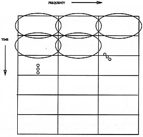
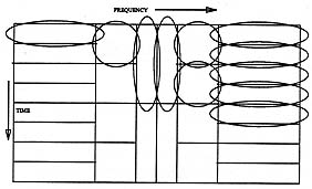
t f (provided that these support measures are quantified in terms of the root mean square deviations from their mean epochs[2]). The time-frequency logon diagrams, depicted in figures 1 and 2 show how the Gabor function bases cover the time-frequency space, and how we can trade frequency resolution for improved temporal resolution. Gabor originally used rectangles to designate each of these elementary signals. If each of these rectangles were a pixel, and its brightness was set in accordance with the appropriate coefficient in the signal expansion (for example by replacing the rectangle with a dither pattern), the logon diagram would be a density plot (image) of the TF distribution.

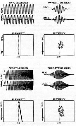
 and fc is a constant (the frequency of the tone in cycles per second).br>
A chirp is a swept frequency where the instantaneous frequency varies with time. Chirps are most familiar as the sound made by a bird or a bat.

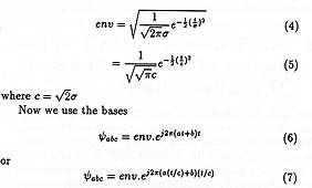
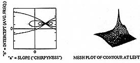
 space akin to the Hiesenberg uncertainty relation in TF space.
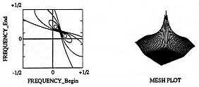
 points.